
A flexible module can follow a curve, yet it cannot correct an inaccurate frame. In projects using flexible LED displays, small structural errors often appear as uneven seams, rippled images, forced module bending, or panels that cannot be removed for maintenance. Good results begin with a support structure designed around the finished display surface, module dimensions, cable paths, and service method.
Define the Flexible LED Display Surface Before the Frame
Start with the display geometry, not the steelwork. A cylinder has a constant radius, while waves, arches, and compound curves may change radius across the surface. Create a full set of coordinates or a 3D model that defines the screen’s visible face. The frame designer can then offset this surface by the combined depth of the LED module, magnetic mount, adjustment hardware, and required clearance.
For flexible LED displays, confirm the finished width, height, curvature direction, viewing distance, and transition points. If the structure is built from a rough architectural outline alone, accumulated tolerance can push the final LED surface away from the intended curve.
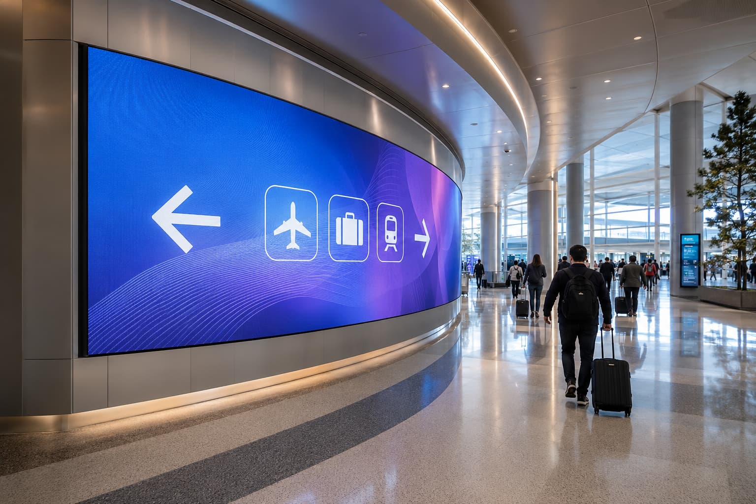
Bend Radius Sets the Flexible LED Screen Geometry
Every flexible LED screen has a permitted bending range. The support frame must stay within the manufacturer’s stated minimum radius without pulling the module into shape. A radius that is too tight can stress the PCB, connectors, masks, and solder joints.
Calculate the required angle for each module position from the target radius and module width. For a faceted subframe, use enough vertical ribs or horizontal rails to keep the deviation between the frame and the true curve within the project’s alignment tolerance. Tighter curves usually require closer support spacing and more adjustment points. Confirm the permitted bending direction; a one-direction flexible panel cannot form a compound curve safely.
Select Frame Material and Stiffness
The frame must hold its geometry under module weight, handling loads, temperature changes, and vibration. Steel offers high stiffness and practical welding for permanent installations. Aluminum reduces weight and can suit modular assemblies, though joint design must control movement and torsion.
Avoid treating the LED modules as part of the frame’s stiffness. Add bracing behind the mounting plane and keep welded distortion away from the module contact surface. Adjustable feet, slotted brackets, or threaded connection points allow installers to correct local depth and angle.
Build the Flexible LED Module Grid from a Datum Line
Curved surfaces make spacing errors easy to accumulate. Establish one vertical and one horizontal datum, then place every module from those references. Do not set each panel only from the edge of the previous panel.
Confirm pixel pitch, then lay out the frame around the actual flexible LED panel dimensions, connector projections, and manufacturing tolerance. Support module corners and edges consistently so adjoining faces remain level. Where a curve joins a flat screen, give the transition its own adjustable support. Inspect seam width with the LEDs both off and on, because bright content can reveal depth differences that are difficult to see during mechanical assembly.
Keep Flexible LED Panels Serviceable from the Front
Magnetic mounting is common in products such as the iFlex Flexible LED Display, but magnets alone don’t provide access. The frame needs an accurately positioned contact surface and clearance for the approved removal tool. A module should lift out without rubbing its neighbors or placing force on the PCB.
Plan access to receiving cards, power supplies, hubs, and connection points as carefully as access to the modules. Divide large screens into service zones and provide labeled cable paths. Components placed behind permanent walls or tightly curved sections may require removable structural panels or dedicated access openings. Test the replacement sequence at the tightest curve before approving the design.
Route Power and Data Without Cable Stress
Cables must follow the structure without resisting the curve. Place power supplies and control hardware where cable runs remain short, ventilated, and accessible. Provide strain relief near module connectors and keep a controlled service loop so technicians can remove a panel without unplugging adjacent rows.
Separate power and data routes where practical, and protect both from sharp metal edges. Avoid compressing cables between magnetic modules and frame rails. On segmented frames, connectors should not sit directly across joints that move during assembly. Document the signal path, power distribution, grounding points, and maximum load per circuit before installation begins.
Protect Outdoor Flexible LED Displays
An outdoor curved screen adds water, heat, corrosion, and wind to the structural calculation. Use suitable finishes and fasteners, and prevent pockets where water can collect behind the modules. Drainage should lead water away from connections. Ventilation must remove heat without directing water toward electrical parts.
Specify the required IP rating for enclosures and connections based on actual exposure conditions. The module face, rear equipment, cable glands, and service doors may need separate protection measures. When a curved section connects to a wider display system, coordinate brightness, weather protection, and maintenance across the installation.
Build and Inspect a Full-Size Sample
A digital model cannot reveal every seam, reflection, magnet position, or removal constraint. Build a full-size sample that includes at least one representative curve, several module joints, mounting hardware, cables, and a service component. Use production materials and the intended fabrication process.
Check the radius, surface depth, seam consistency, module removal, cable clearance, and image continuity. Run bright solid colors, fine grids, and moving content to expose alignment errors. Record any required frame corrections, then update the fabrication drawings before mass production. This step is especially valuable when a project includes changing radii or transitions between curved and flat surfaces.
A Stable Support Structure Protects Flexible LED Display Quality
The support structure determines how well flexible LED displays keep their intended curves, clean seams, and practical maintenance access. A reliable design starts with exact surface geometry, respects the module’s bend limit, holds every mounting point to a shared datum, and leaves room for cables and front service. Consider environmental loads and water management when the screen is outdoors. Once a full-size sample confirms these details, the production frame can support consistent image quality without forcing the modules to compensate for structural errors.