
A 3D kinetic LED screen is made from many LED units that move forward and backward independently. That movement creates real depth, but it also creates a challenge: the audience should still see one connected image, not a collection of separate moving blocks. The screen maintains that seamless appearance by controlling several things at once. The modules must stay aligned, their gaps must remain consistent, and each unit must receive the correct part of the video. Movement must also match the content, while brightness and color must stay even across the display. This means “seamless” doesn’t always mean there is no physical gap. Moving modules need clearance to travel safely. The real goal is to stop those gaps from breaking the image or drawing attention away from the content. A well-designed 3D kinetic LED display makes hundreds of moving parts look like one changing digital surface.
What Makes a 3D Kinetic LED Screen Look Seamless?
Viewers judge continuity by what they can see. If a line passes across several modules without jumping, a logo keeps its shape during movement, and neighboring modules show the same colors, the screen feels connected.
Several conditions are therefore needed:
- Module gaps should be narrow and visually consistent.
- Each unit should move along a straight, predictable path.
- Modules should stop at the intended position and return accurately.
- Pixel mapping should place the correct image area on every module.
- Video playback and mechanical movement should follow the same timing.
- Brightness, color, and grayscale should match across the screen.
One weak area can affect the whole result. Video mapping cannot hide a tilted module, while mechanical alignment cannot correct a visible color difference. The seamless effect comes from the complete system.
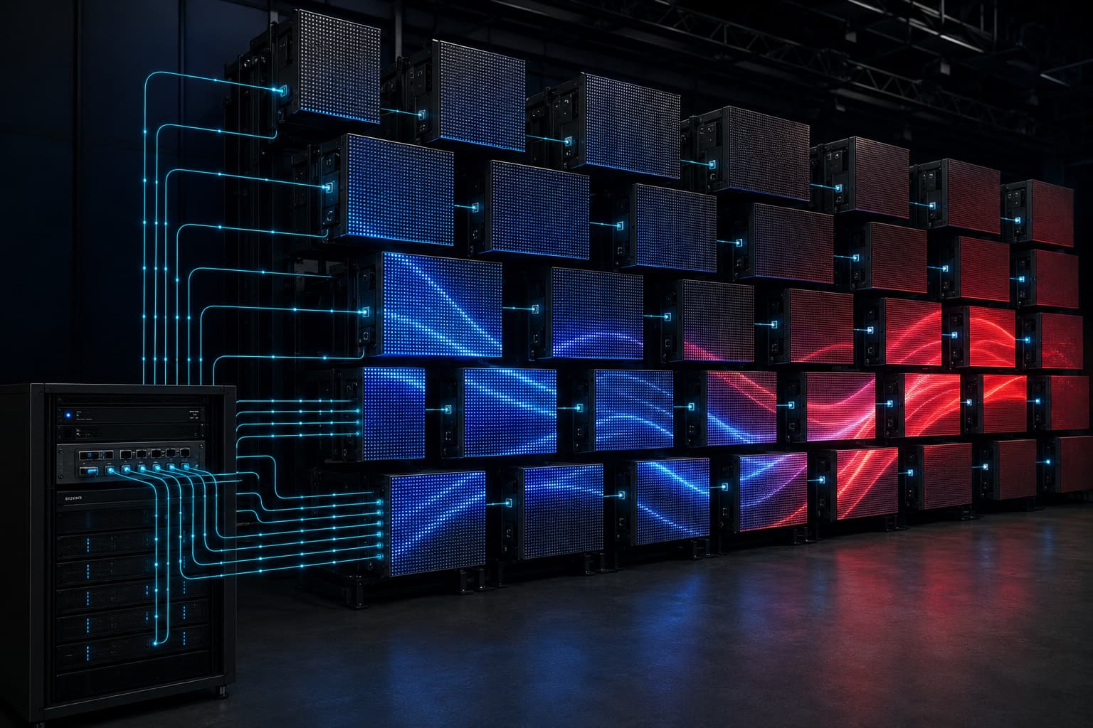
How Precise Movement Keeps a 3D Kinetic LED Screen Aligned
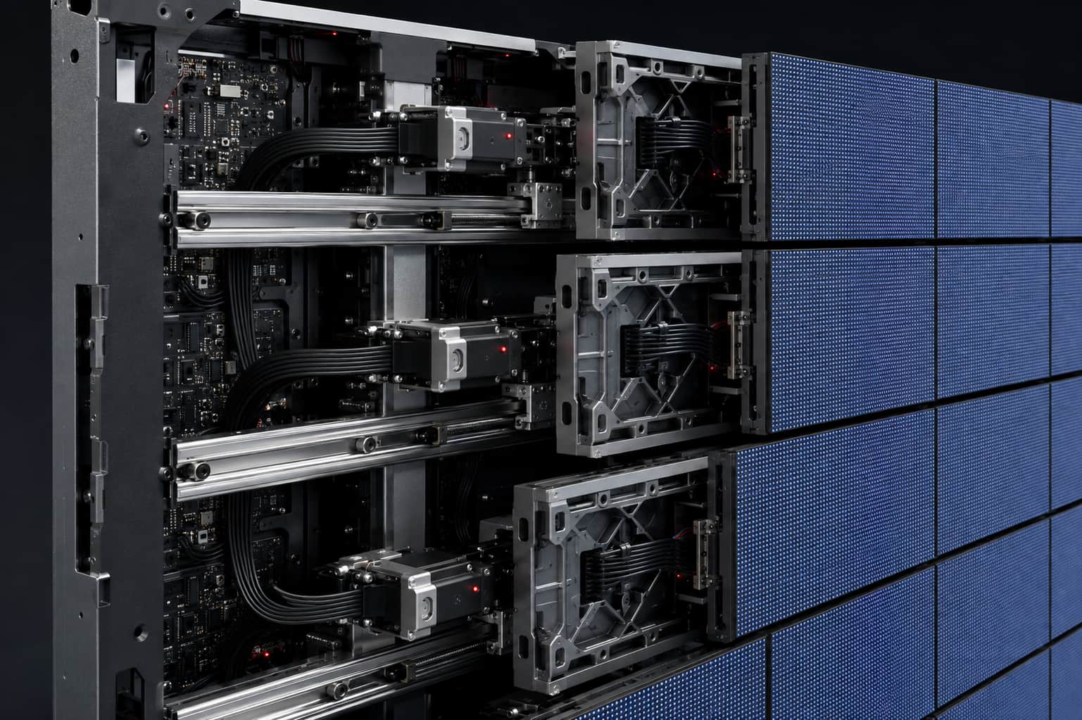
The image starts with the physical structure. Every module needs a clear starting point, a controlled travel path, and an accurate stopping position. If one unit shifts sideways, tilts, or stops at the wrong depth, the picture may appear broken even when the video signal is correct.
The Cabinet and Guide Rails Keep Modules Straight
A rigid cabinet gives the motion units a stable base. Good cabinet flatness helps the modules begin on the same plane and keeps neighboring gaps even. On a large display, this also limits the buildup of small installation errors. Industrial guide rails keep each module on its intended path. It should travel without drifting sideways or tilting. This keeps image edges in the expected position and prevents sudden changes in the visible gap. Installation quality matters as well. A precise cabinet can still produce uneven seams if the supporting frame is twisted or adjacent cabinets are misaligned. The frame, cabinets, rails, and modules must all share the same reference plane before motion programming begins.
Repeatable Movement Prevents Changing Gaps
A seamless image must remain consistent through repeated motion cycles. Modules must repeat the same travel distance, stop at the same points, and return to the same starting surface. Repeatable movement prevents the gaps from gradually changing. It also gives content designers a reliable structure for timing video transitions. JR Visual explains more about the relationship between movement accuracy and image stability in its guide to how a 3D kinetic LED screen moves while keeping the image stable.
How Pixel Mapping Keeps the 3D Kinetic LED Screen Image Connected
Mechanical accuracy keeps the modules in the right place, but the control system decides what each module displays. Pixel mapping divides the complete video canvas among the LED units. When that map is correct, the audience sees one picture extending across the full screen.
Each Module Receives the Correct Part of the Image
Every LED unit has a defined position in the layout. The control system sends the correct pixel group to that position. When a line crosses several units, the separate sections must meet in the correct order. A mapping error can reverse a module, place it in the wrong row, or send it the wrong image area. Text, circles, and product outlines may then break at the edges. Grid patterns and numbered module maps help you find these errors before loading final content. Check the mapping again after replacing a receiving card, LED module, or control component. A repair may restore the hardware but still leave the picture out of sequence if you don’t load the original configuration correctly.
Video and Motion Must Stay in Step
Plan the motion program and video timeline together. If either starts early, the image transition will not match the screen’s physical position. Start time, speed, travel distance, pause time, and return time all affect continuity. Smooth acceleration and deceleration also help because sudden changes can make small alignment errors more visible. Each module must be where the content expects it. A rotating LED display uses a different form of movement, but it follows the same basic timing principle. Screen position and video content must stay coordinated. A rotating LED screen may change its viewing angle, while a forward-moving kinetic screen changes its depth. In both cases, accurate timing keeps the visual sequence easy to follow.
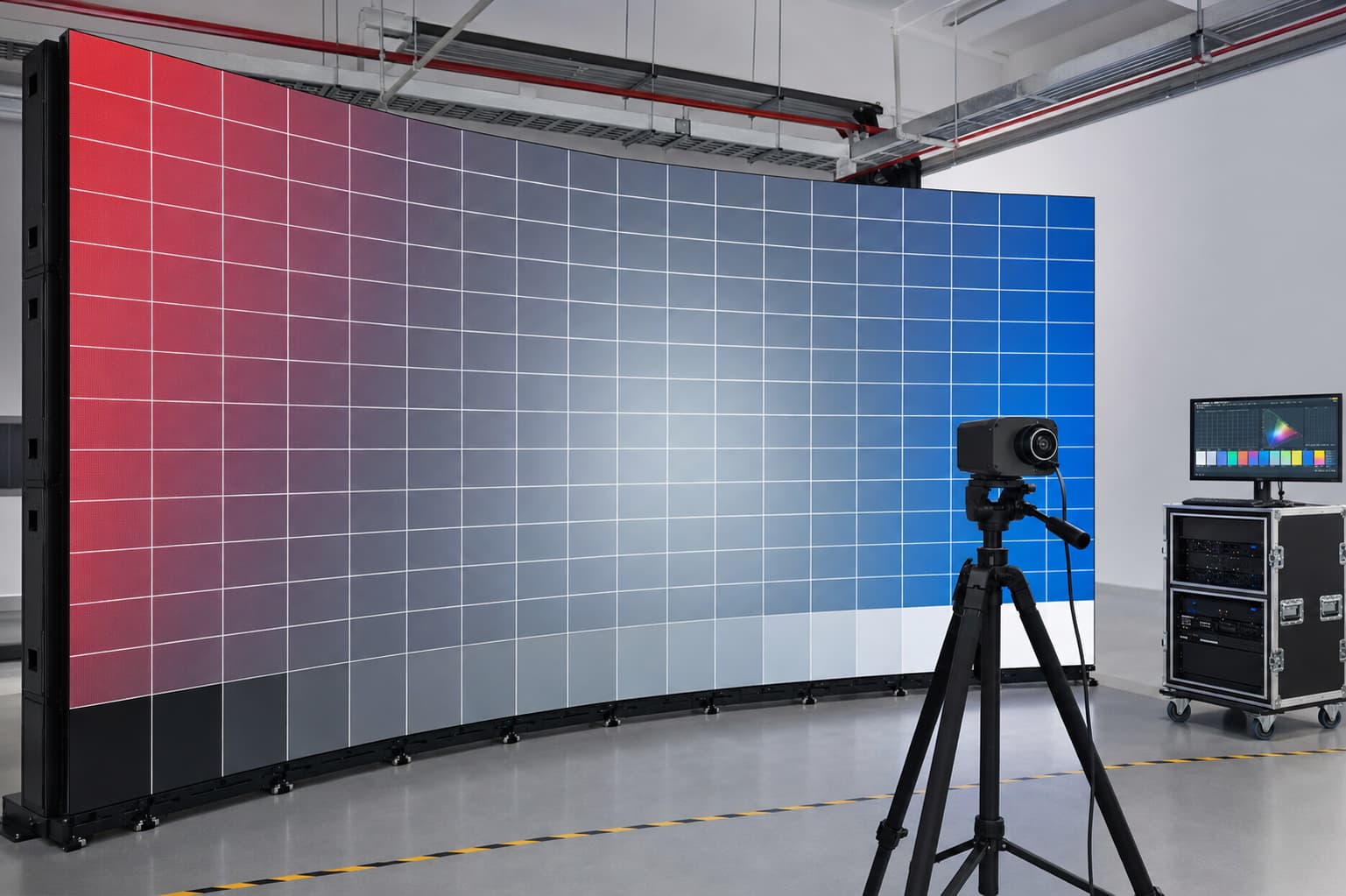
How Calibration Makes a 3D Kinetic LED Screen Look Uniform
Even a perfectly calibrated screen can show visible module boundaries when brightness or color differs from one unit to the next. A slightly darker module can look like a separate square. A change in white balance can create a warm or cool patch that remains visible throughout the video.
Matching Brightness and Color Hides Module Borders
Calibration corrects LED module output so it responds more evenly. Check brightness, RGB balance, color temperature, and grayscale across the display. White images reveal color differences, while gray and low-brightness images expose uneven output. Pixel-level or module-level correction can make the surface more uniform. This is especially useful after a module replacement, because the new unit may not match its neighbors. NovaStar’s official overview of creative display calibration also shows why irregular display shapes need suitable calibration methods rather than a simple visual adjustment. Calibration cannot repair a physical gap or a tilted module. It solves a different part of the problem: making neighboring display areas produce similar light and color. Mechanical correction and visual calibration therefore need to be checked separately.
Content Design and RCalibration Protect the Final Result
Content can hide small physical divisions or make them more visible. Fine text, high-contrast lines, and detailed product edges are sensitive to alignment errors. They should not cross areas with the greatest movement unless tested on the real screen. Waves, particles, gradients, and fluid animations often work well because they can follow module movement. Content should use the actual screen resolution, module layout, travel direction, and movement sequence. The same planning applies to rotating displays. Content for a rotating display should account for changing angles and viewing positions, while content for forward-moving modules should account for changing depth. Using one generic video for every kinetic format rarely produces the best result.
Regular checks are needed to preserve the seamless appearance after installation. A practical inspection can include:
- Play a grid pattern and check whether lines remain straight across module edges.
- Use full-white and gray images to look for brightness or color differences.
- Run the complete motion sequence and watch the start, stop, and return positions.
- Repeat the same sequence several times to check movement consistency.
- View the display from the closest expected audience position and from both sides.
- Recheck mapping and calibration after replacing a module or control component.
Standard test calibration makes these checks easier to repeat. ITU-R BT.814 describes test signals and alignment procedures for display brightness and contrast. A kinetic installation also needs motion tests, but the same principle applies: use defined test images instead of relying only on promotional content. Consider mechanical access before completing the display. Technicians need enough space to inspect motion units, cables, power supplies, and control components without disturbing neighboring modules’ alignment. Include these requirements in the safe kinetic LED display installation plan rather than leaving them for the first repair.
A 3D kinetic LED screen maintains a seamless image because every part of the system supports the same visual goal. The cabinet and guide rails keep the modules aligned. Repeatable movement keeps the gaps consistent. Pixel mapping connects the picture, synchronization matches the video to the movement, and calibration keeps brightness and color uniform. Content design and routine calibration protect that result during real operation.
FAQ About Seamless Moving LED Images
Can a 3D kinetic LED screen be completely gapless?
Moving LED modules need a small amount of clearance, so a true zero-gap surface is generally not practical. A seamless result comes from keeping the gaps narrow, even, and visually unobtrusive at the intended viewing distance. Accurate alignment, suitable content, and consistent module output help the audience perceive one connected screen.
Why do the seams become easier to see while the screen is moving?
Movement changes module depth and viewing angle, which can make a small gap more visible. Seams may also stand out when a module tilts, stops at the wrong position, moves at the wrong time, or displays a different brightness or color. Watching the full motion sequence with grid and gray test images helps identify the actual cause.
Does a smaller pixel pitch automatically make the image seamless?
No. A smaller pixel pitch can improve detail at a close viewing distance, but it cannot correct uneven gaps, mechanical drift, incorrect pixel mapping, timing errors, or color differences. You need to consider pixel pitch, structure, control, calibration, content, and viewing distance together.