
A glass wall can carry digital content and still serve as a window, but the project team has to protect both functions. Buyers often compare one brightness figure with one transparency figure and stop there. That approach overlooks the glass type, sun exposure, viewing distance, structural load, cable route, and maintenance access that shape the final result. A transparent LED film display should therefore be part of the facade or storefront brief. The display team, architect, contractor and content owner need the same dimensions and operating conditions before anyone selects a pixel pitch or product family.
Start the transparent LED film display brief with the glass.
Record the visible glass area, individual pane dimensions, mullion positions, glass build-up and permitted fixing method. Confirm which face of the glass can receive equipment and which areas must stay clear for doors, vents, safety markings or cleaning access. Curved or irregular glass also needs a physical survey because a drawing may omit joints, coatings or local changes in radius. The survey should also capture orientation and external obstructions. A north-facing lobby, a shaded mall atrium and a west-facing shop window place very different demands on content visibility. Photograph the glass at planned operating hours and measure locations for power supplies, receiving cards, and service access. These inputs narrow the viable structures before product comparison begins.
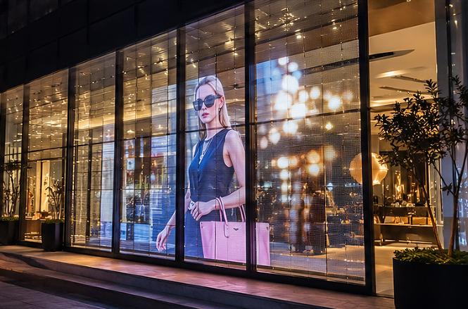
Balance transparent LED film screen brightness and transparency
Higher transparency keeps more of the view and daylight, while higher LED density can improve image detail. The relationship is not a simple slider. LED package size, spacing, circuit layout, supporting structure and the original glass all affect the final view. The glass itself already has a measurable Visible Transmittance, so the team should evaluate the complete assembly instead of treating a display transparency percentage as the window result. Brightness also needs time and direction. A screen that looks strong in a showroom can lose contrast when direct sun hits the glass, or it reflects off the street. Ask suppliers to demonstrate representative content under a light level close to the site condition. Review the display from the intended approach path, from inside the building and from oblique angles. Run the same test with the display off to judge how much hardware remains visible.
| JR Visual family | Structure | Published brightness | Published transparency | Typical placement |
| StarLink | Adhesive LED film | Up to 7,000 nits | >50% | Indoor or behind glass |
| TF Series | Flexible PET film | >3,000 nits | >85% | Flat or curved indoor glass |
| iTLED | Modular panel | 5,500 nits | 79-89% | Indoor or semi-outdoor |
| X-TLED | Weatherproof cabinet | 6,500 nits | 50-58% | Outdoor facade |
These figures are product-family ranges published on the Transparent LED Display page. Confirm the selected model, configuration, protection level, brightness and transparency on the approved project datasheet before ordering.
Choose the right structure for a transparent LED film display.
Adhesive film, flexible PET film, and cabinet-based transparent panels solve different installation problems. A transparent LED film screen can attach directly to suitable glass and reduce the amount of visible support structure. A flexible transparent LED display can follow selected curved or irregular surfaces when the approved bend and fixing conditions match the glass. A modular cabinet system gives the installer a defined frame, repeatable panel geometry and a clearer replacement route. It also adds depth and structural interfaces that a film system may avoid. Outdoor work usually pushes the decision toward an engineered cabinet or strip structure. The outdoor transparent LED display family, for example, addresses facade installations with a dedicated outdoor structure. Select the structural route first, then compare pixel pitch within that route. This sequence prevents the team from choosing a fine pitch that cannot fit the glass, cooling, weight or service plan.
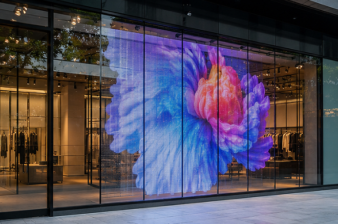
Match pixel pitch to viewing distance and content
Pixel pitch affects how close viewers can stand before the pixel structure becomes distracting. It also changes transparency, wiring density, power distribution and cost. A luxury storefront viewed from the pavement may need finer detail than a media facade viewed across a road. A large logocolour field or silhouette can remain legible at a coarser pitch, while product photography, small typography and faces need tighter control. Create sample content at the proposed screen’s actual pixel dimensions. Test large type, product edges, skin tones and dark backgrounds. Avoid judging the display with a supplier reel alone because that reel may use content prepared for the panel. A short content test shows if the planned creative work survives the chosen pitch and transparency.
Plan installation and service access before approval
The installation drawing should show each film or panel section, power location, signal route, controller position, cable transitions and access zone. Confirm how installers will align sections across mullions and protect glass edges. The team should also define the cleaning method and identify any chemicals, tools, or pressure the display supplier excludes. Service planning needs a real removal path. Ask which component fails independently, what space a technician needs, and how a replacement reaches the screen after furniture, shopfitting or facade finishes are complete. A lightweight product can still create a long shutdown if the service path sits behind a permanent ceiling or display fixture.
- Confirm the glass composition, surface condition and approved attachment method.
- Mark power, data and controller locations on the coordinated drawing.
- Verify the finished load and fixing method with the responsible project engineer.
- Define access for module, power-supply and control-component replacement.
- Run a daytime and nighttime content test before final acceptance.
Avoid four common specification mistakes
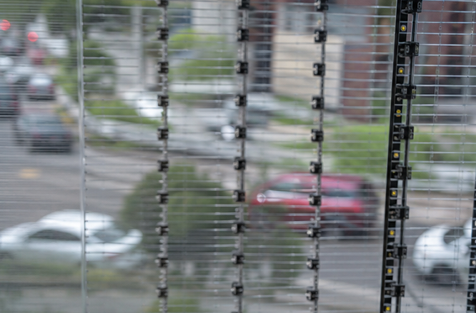
Comparing headline transparency figures alone: Two products can publish similar transparency figures and still look different after installation. Supporting strips, cable paths, controller boxes, glass coatings and viewing angle change what people see. Request a full assembly sample or a representative installed area.
Selecting brightness without a site test: Brightness should answer a defined ambient-light problem. Excess output can create uncomfortable indoor viewing and unnecessary operating demand, while low output can disappear in a sunlit window. Set daytime and evening operating targets and include dimming behaviour in the test.
Choosing fine pitch before checking viewing distance: A finer pitch can raise cost and component density without improving the experience at a long viewing distance. Test the content from the nearest and most common viewing points before approving the resolution.
Leaving maintenance until the shopfit is complete: Access often disappears when shelving, ceilings or facade trims close around the display. Include the service route in the coordination drawing and keep the required clearance free throughout construction.
A good glass display decision starts with site evidence.
The strongest specification connects the glass survey, ambient light, viewing distance, content format, structural route and service plan. Once those inputs are fixed, the team can compare brightness, transparency and pixel pitch with a clear purpose. Send JR Visual the glass dimensions, installation environment, viewing distance and operating hours to narrow the structure and configuration for the project.