
A curved display can follow a column, wrap a stage, form a wave, or soften a retail corner. The visual idea may look simple in a rendering. Still, the installation depends on several connected decisions: the actual radius, module dimensions, support geometry, seam direction, cable routing, viewing position, and service route. Problems usually appear when a team selects the LED product before measuring the surface. A small difference between the architectural model and the built structure can create stepped edges, open seams or forced modules. Good curved LED screen planning starts with site geometry and works inward toward the module grid.
Start Curved LED Screen Planning with Measured Geometry
Record the finished radius rather than relying only on a concept drawing. Measure several points along the curve because walls, columns and fabricated frames may vary from one level to another. State whether the surface is concave, convex, cylindrical, wave-shaped or a compound form. A single radius cannot describe a surface that changes direction. The survey should include the available depth, top and bottom boundaries, nearby doors, trims, sprinklers, ventilation and cable entry points. Mark the intended front face of the display and the structural attachment plane separately. That distinction prevents the support frame from consuming the space reserved for modules and service access.
For a freestanding installation, record floor loading, ceiling restrictions and movement paths for delivery. For an existing wall, identify the substrate and the points where a qualified project engineer permits attachment. Photos should include oblique views, straight elevations and reference dimensions.
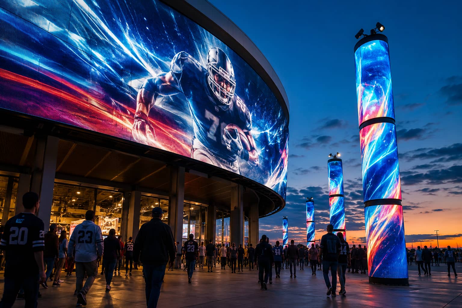
Translate Radius into a Flexible LED Module Layout
The module dimensions determine how closely the display can follow the requested curve. Lay out complete modules along the arc and calculate the resulting angle between adjacent units. Compare that geometry with the approved bending or mounting conditions for the selected product. Never force a module beyond the supplier’s documented limit to make the last section fit. Start the grid from a visual datum such as the centerline, a doorway or a major architectural joint. Then check the remaining width at both edges. A narrow leftover strip may require a change to the display width, radius or edge treatment. Making that decision on the drawing is cheaper than discovering it after the support frame is fabricated.
The JR Visual product details page maps Flexible LED Display terms to the LED module range. Buyers should still confirm the chosen module size, permitted geometry, mounting method and indoor or outdoor suitability on the project datasheet before ordering.
Design the Curved Screen Support Structure Before Mounting
The support structure establishes the final curve. It needs defined datums, adjustable points and tolerances that the installer can check. If the frame varies, flexible modules will reproduce the error instead of hiding it. A smooth front surface begins with repeatable ribs, rails or mounting plates behind the display. Divide responsibility clearly. The display supplier can provide module and interface requirements, while the responsible structural team must assess loads, attachment points and site conditions. Include the screen, frame, power components, cables and any service platforms in the review.
Temporary lifting also needs a planned method. Requirements such as rigging equipment inspection apply within their relevant jurisdiction and should be coordinated with local rules. Allow adjustment without creating weak or inaccessible connections. Installers need a way to correct small site deviations while keeping modules aligned. The drawing should show how the first row is established, how each section references the previous one and how the completed arc is verified.
Protect Seam Quality Across the Curve
Curved screens expose errors differently from flat walls. A vertical joint may look acceptable from the centre but open when viewed from the side. Module height, magnetic seating, frame tolerance and cable pressure can all move the front surface. Inspect seams from the main viewing area and from the approach paths that matter to the project. Build a representative curved section before releasing the full frame. Use the planned radius, module orientation and mounting hardware. Display bright fields, dark fields, horizontal movement and fine edges. This sample reveals mechanical steps, brightness transitions and content distortions that a static black screen can hide. Do not solve a recurring seam problem through image calibration alone. Calibration can improve luminance and colour consistency, but it cannot correct a physical angle, uneven module depth, or a stressed mounting point. Record mechanical acceptance criteria separately from image-performance checks.
Match Pixel Pitch and Content to the Viewing Arc
The nearest viewer and the content type should guide pixel-pitch selection. A curved screen around a reception desk may be viewed at short distance from several angles. A stage backdrop may sit much farther away. Compare candidate modules using the real screen resolution and the closest normal viewing position. Curvature changes composition. Content near the edge may face away from a central viewer, while a message designed as one flat canvas may stretch across the arc. Create test files at the actual pixel dimensions and place important faces, logos and product details within the useful viewing zone. Avoid putting small text across great changes in direction. Review the broader LED Display Products range when the project includes both curved and flat areas. The Creative LED Display category can also help teams compare a flexible module approach with other custom shapes before the structure is fixed.
Plan Cable Movement and Service Access Behind Flexible Modules
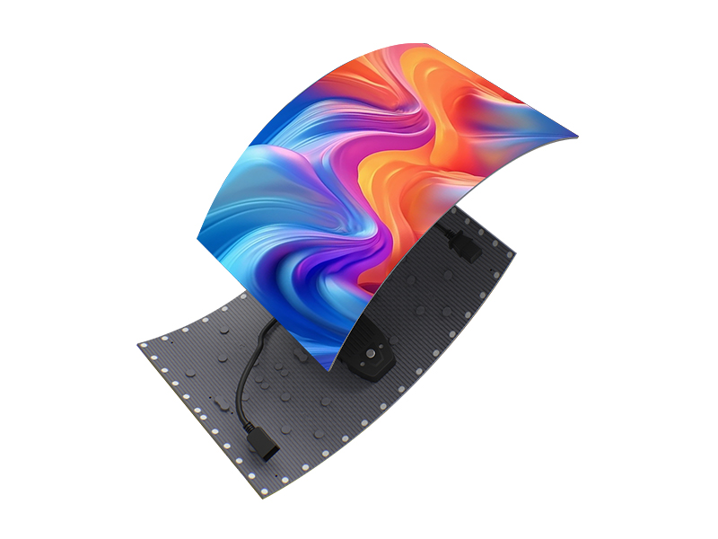
For a Curved LED Screen, power and signal cables should follow the curve without pulling modules away from their seats. Show bend space, strain relief, connector orientation and the route between structural sections. Keep cables clear of sharp edges and moving service paths. A neat front surface can still fail inspection when the rear installation compresses connectors or blocks replacement. Define which component can be removed first. Front-service modules may reduce rear clearance, but technicians still need access to power supplies, receiving components and cable junctions. Test the removal path on the curved mock-up. A module that releases easily on a bench may collide with its neighbours when installed on a tight concave surface. Create a position map for modules and electronics. Record configuration files and replacement procedures with the final project documents. These controls shorten troubleshooting and reduce the risk that a replacement part receives the wrong address or orientation.
Approve a Curved LED Screen with Geometry and Content Evidence
Final approval should compare the built radius, module alignment, seam quality, image consistency, service access and tested content with the released drawings. Inspect the screen from the central position, both ends of the arc and the normal circulation route. Run the planned content instead of relying only on solid-color test patterns. The right decision comes from the full installation, not a single module specification. Use the LED Display Solutions overview to place the display within the wider venue requirements, then send JR Visual the measured radius, screen dimensions, viewing distance, installation environment and service constraints for a module-layout review.