
A floor LED display load specification must treat the system as both an image surface and a walking or equipment platform. Its visual specification cannot be separated from structural load, surface grip, edge transitions, water and dirt exposure, sensor performance, and service access.
The Floor LED Display Load Decision
The required rating depends on the largest point load, contact area, movement, impact, frequency, and supporting structure. A pedestrian floor, rolling equipment route, stage, and vehicle display cannot use the same acceptance assumption. The system also needs a defined method for lifting one panel, reaching electronics, cleaning the surface, and restoring sensor calibration. The checklist below helps venue, structural, AV, and maintenance teams define those requirements before ordering.

Define Floor LED Display Load Conditions
List every expected load: pedestrians, crowds, performers, rolling cases, trolleys, scenery, furniture, lifts, or vehicles. Record individual wheel or foot contact areas, maximum point load, distributed load, movement, impact, and frequency. Review the available panel format through led flooring while keeping project acceptance limits in the engineering brief. The structural engineer and system supplier should agree on the load path from the panel surface through cabinets, supports, leveling components, and building floor. Do not treat a published load figure as approval for every wheel size or dynamic condition. Define restricted activities such as jumping, sharp heels, dragging metal edges, or placing outriggers directly on panels. Use load-spreading plates where the approved design requires them.
Surface Grip and Floor LED Display Safety
Review the surface finish under dry and expected contaminated conditions. Dust, water, cleaning products, haze fluid residue, or outdoor moisture can change grip. The selected test method and acceptance requirement should match the venue and local regulations. Plan ramps, trims, guard edges, and transitions to adjacent flooring. Avoid abrupt level changes and exposed corners. Cable exits, access openings, and temporary covers should not create trip points. Inspect the mask or protective surface for scratches, haze, damaged texture, and looseness. Define replacement criteria because wear affects both safety and image appearance.
Supporting Structure for Floor LED Display Installation
Survey the base floor for level, capacity, drainage, access, and penetrations. The substructure should allow accurate panel alignment without unstable shimming. Record the permitted finished height and how ramps will fit into the room. Define power and data routes below or beside the display. Protect cables from load, sharp edges, water, and service activity. Provide earthing, circuit protection, and accessible isolation. For outdoor or wet-cleaning environments, review ingress paths at panel seams, connectors, cable entries, and low points. A cabinet rating alone does not define the assembled floor system. If an IP rating is specified, define the required enclosure protection and verification method with reference to the IEC 60529 IP Code, together with local electrical and venue requirements.
Viewing Geometry for Floor LED Display Installation
Review the indoor LED screen when a project combines floor surfaces with conventional wall displays. Audience members often see the floor at oblique angles. Test brightness, contrast, reflections, and color from standing height and the planned camera positions. A very glossy surface may preserve apparent contrast from one view while producing distracting reflections elsewhere. Choose pixel pitch from the closest meaningful viewing distance, content detail, camera use, and floor dimensions. Verify low-level gradients and dark scenes because surface texture and overhead lighting can affect uniformity. Content should account for feet, props, and people blocking the image. Large forms and responsive motion often work better than small text or details that disappear under users.
Interaction and Floor LED Display Safety
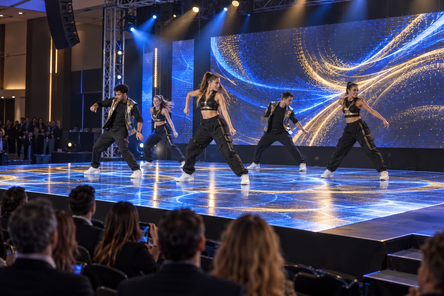
Interactive floor concepts can be coordinated with the wider Creative LED Display and creative lighting solutions when the venue uses several unusual screen forms. For an interactive LED floor, define the sensing technology, active zones, response time, maximum simultaneous users, tracking behavior, and failure mode. Test typical shoes, slow and fast movement, standing groups, props, and boundary conditions. Create an interaction map that matches the final pixel map and physical panel addresses. Verify calibration after replacing modules or panels. The content system should handle temporary sensor loss without freezing the full show. Record the software version, input protocol, coordinate system, media-server configuration, and recovery procedure. Test interaction with final or representative content, not only a diagnostic cursor.
Cleaning and Floor LED Display Maintenance
Define approved cleaning tools, liquids, frequency, drying time, and inspection. Liquids should not pool at seams or cable areas. Abrasive methods can change surface grip and optical appearance. Confirm how to remove one panel or module, how much space the tool needs, and whether people can walk nearby during service. Keep spare masks, modules, power supplies, receiving cards, sensors, and cables based on the project risk and operating schedule.
Use acceptance checks for level, gaps, rocking, surface damage, load testing where specified, grip, image calibration, interaction zones, ingress controls, cable protection, emergency isolation, and service access. Send JR Visual the floor dimensions, base-floor information, maximum point and distributed loads, wheel types, expected traffic, indoor or outdoor conditions, interactive functions, viewing distance, camera requirements, and maintenance window. The team can prepare a project-specific specification from these inputs.
Floor LED Display Load Questions
How is the required load rating determined?
It is determined from the heaviest person, prop, wheel, cart, stage element, or vehicle that may contact the floor. Buyers should specify both distributed load and concentrated point load, including dynamic movement and safety factors required by the project engineer.
Is a distributed rating enough for wheeled equipment?
No. A small hard wheel can create a much higher local pressure than a person standing on the same area. Review wheel diameter, tread material, axle load, turning behavior, and travel path separately.
What maintenance access should the system provide?
The design should allow access to failed panels, modules, sensors, power supplies, receiving cards, and cables, and allow replacement within the available maintenance window without damaging adjacent floor sections.
What should be included in the RFQ?
Include floor dimensions, substrate condition, point and distributed loads, wheel data, traffic pattern, environment, interaction requirements, cleaning method, viewing distance, and service restrictions.